Back to the Radio Pages


Here is series 
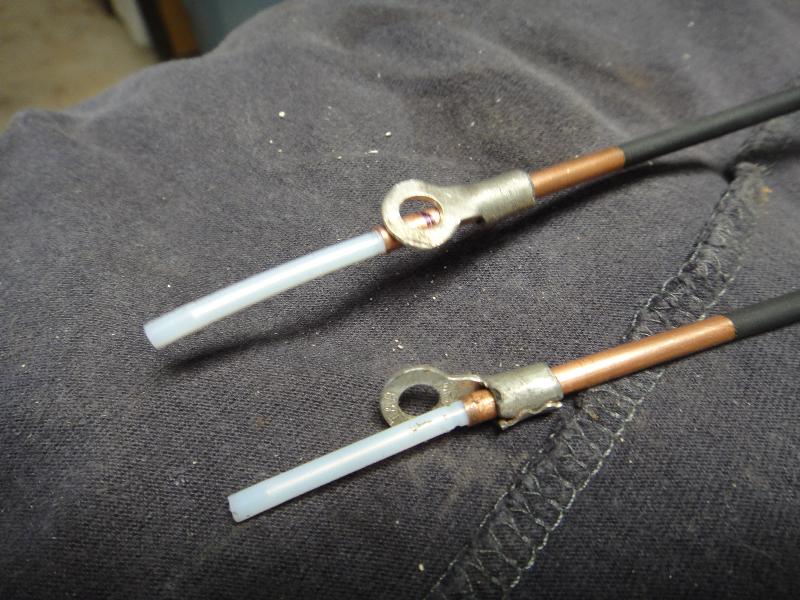
of photos that attempt to detail how the feed point for my YU7EF yagi on 144 MHz was made.
Only common hand tools were used in the process


The Bracket begins
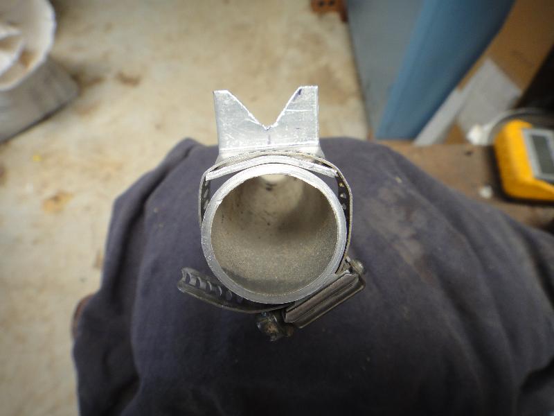
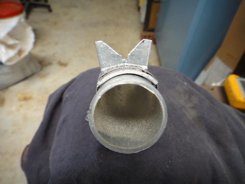
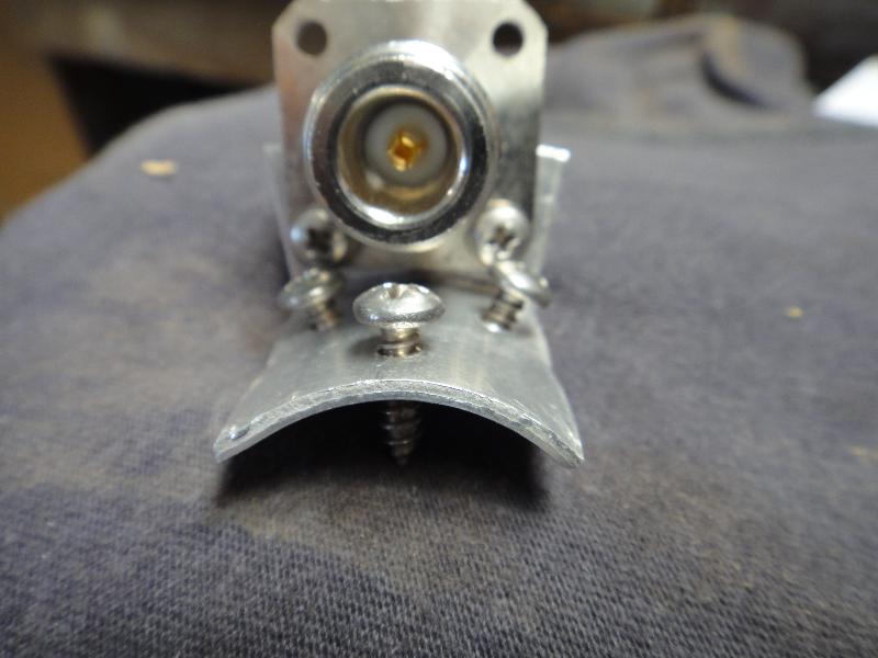
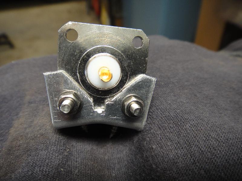
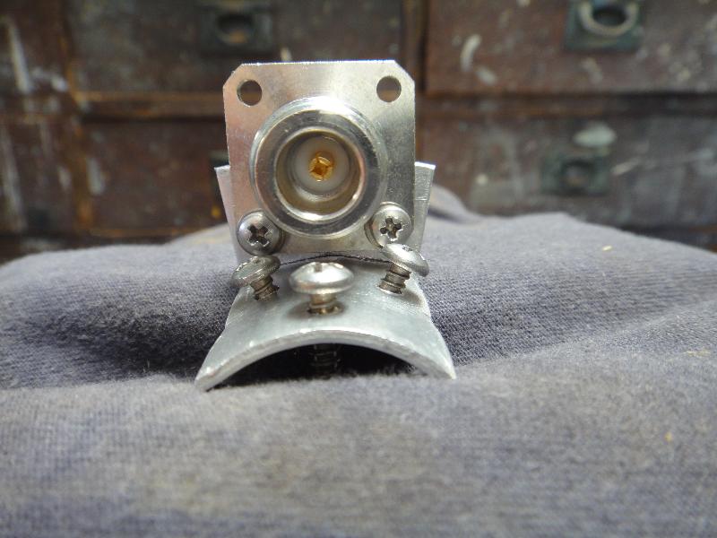
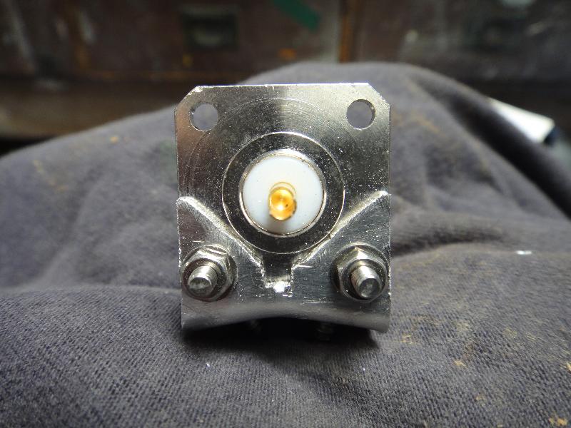
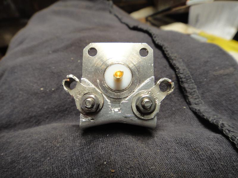
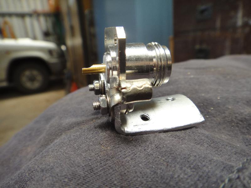
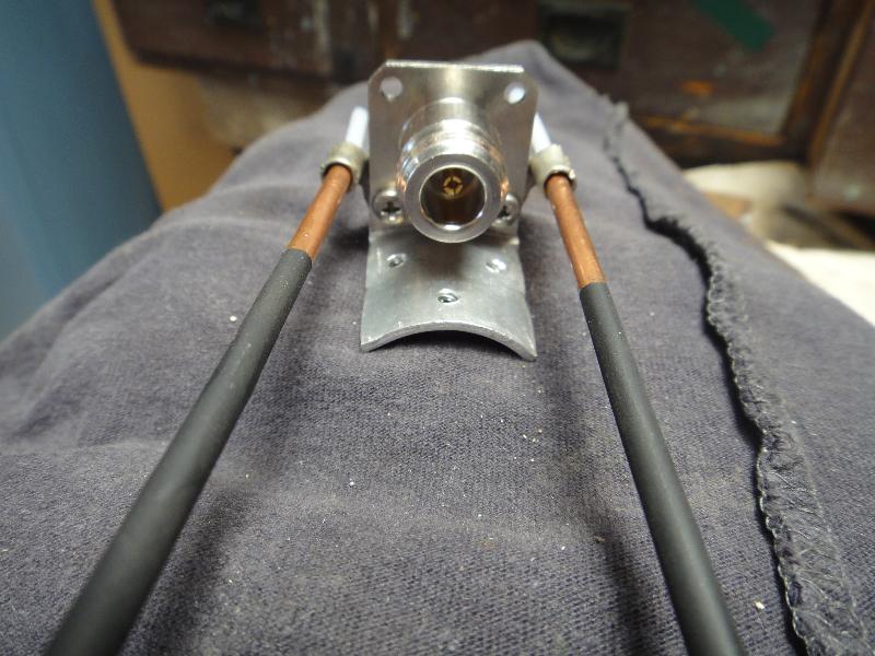
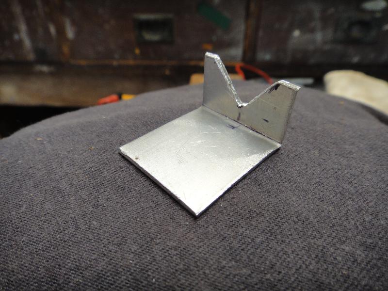
The bracket starts life as a strip of aluminium plate that is 25.4mm wide (the same as a typical flange N socket) and 45mm long.
The bend is 15mm from one end and the V is cut with a small hacksaw then cleaned up with a file. (front view)
moulding it to the shape of the boom
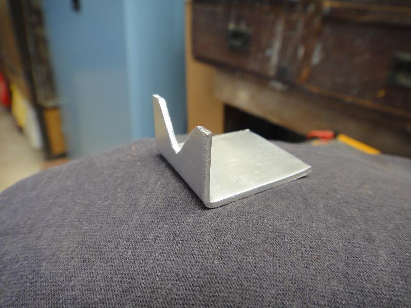
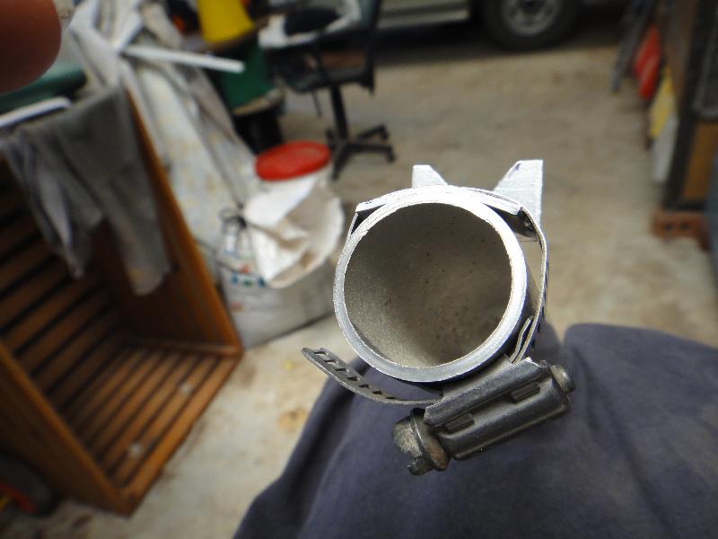
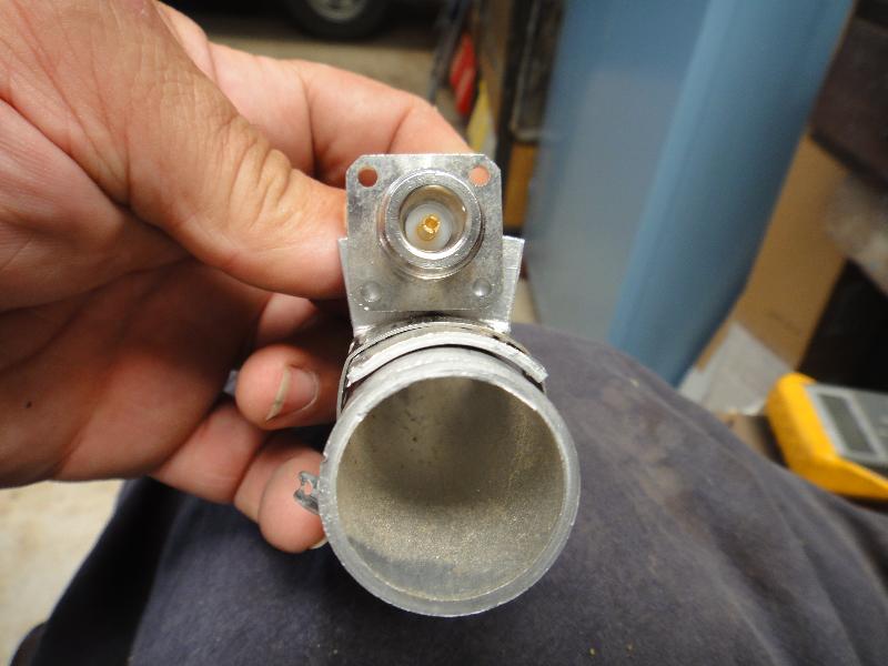
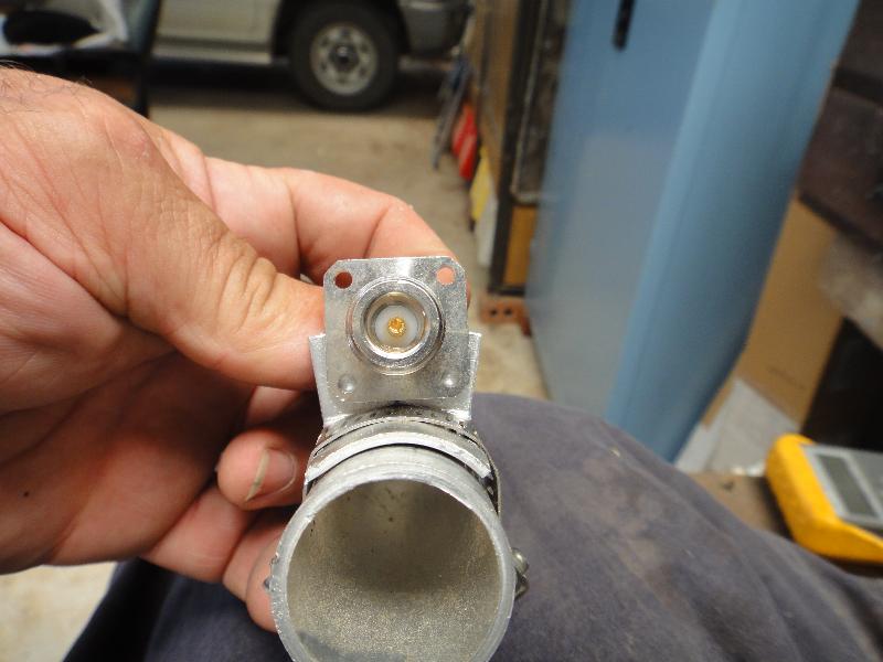
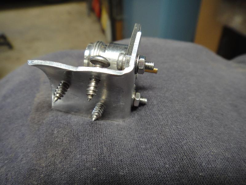
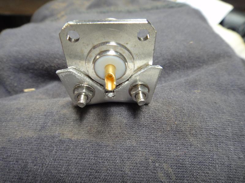
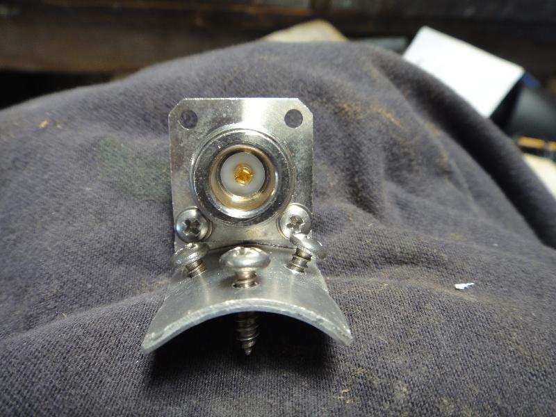
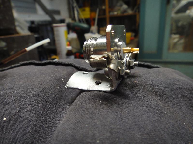
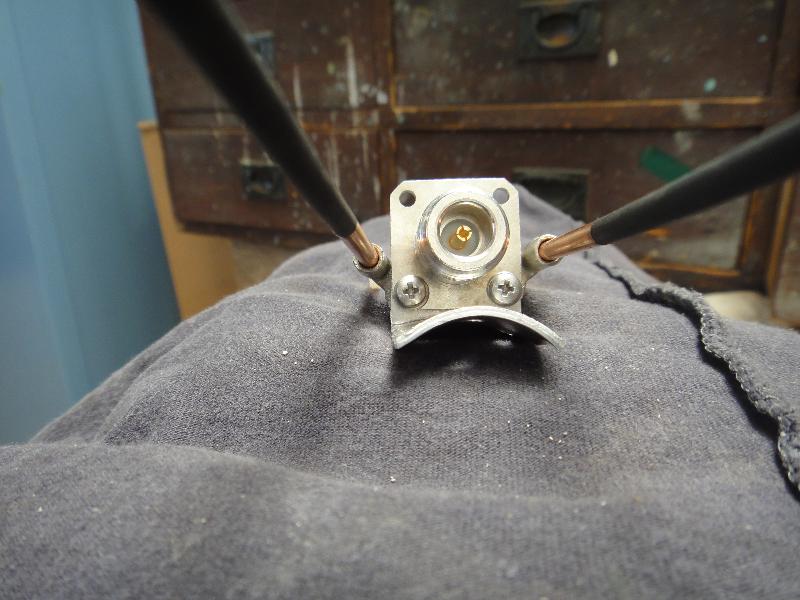
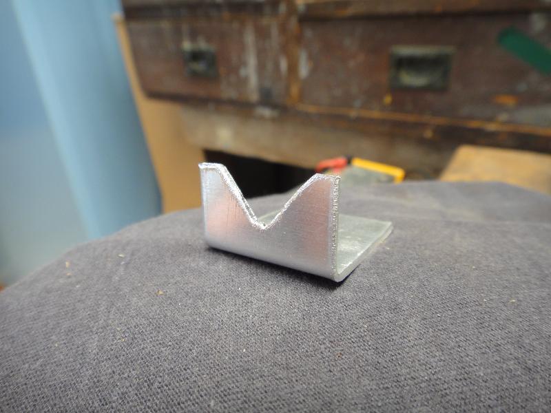
Rear view of the bracket after cleanup
slow bend to mate the boom
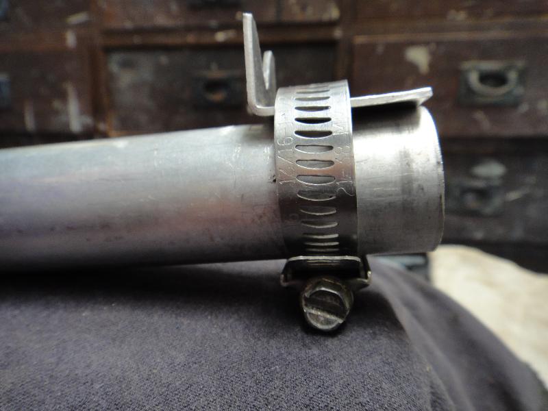
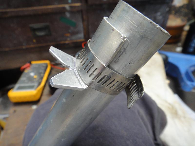
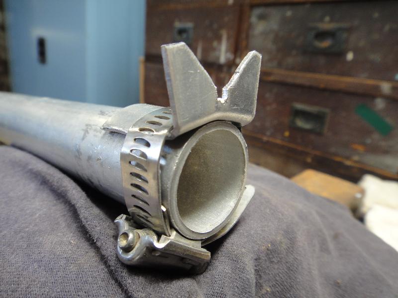
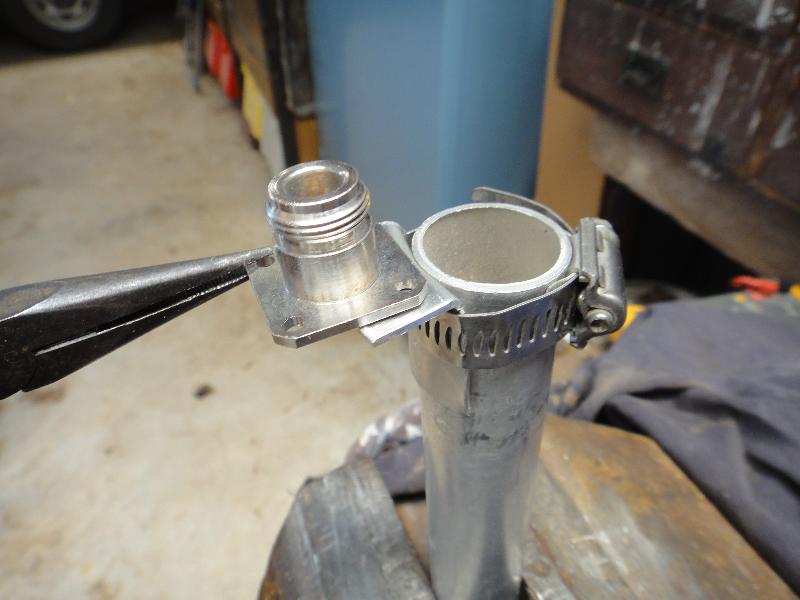
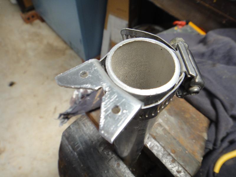
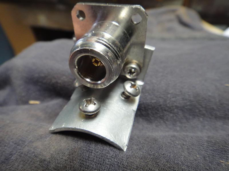
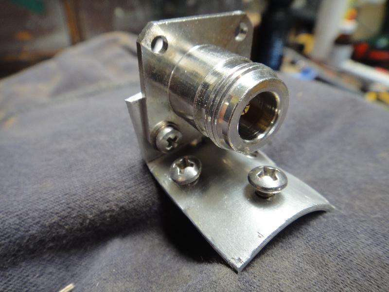
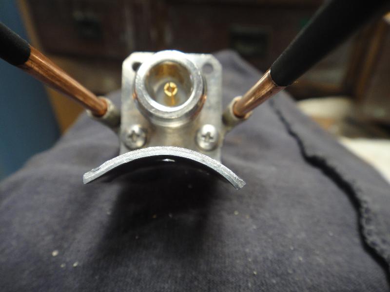
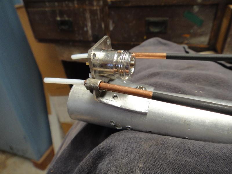
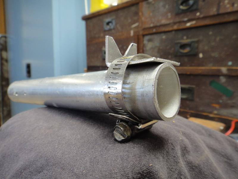
Now we want to mould the bracket so it fits snugly onto our round boom.  A worm drive clamp does the job neatly and with out the need for force.
an N socket held in place to give some ide of size
The N socket being used to mark the holes
basic assembly of the bracket and mounting screws
diferent angle of the basic bracket
rear view of the basic bracket