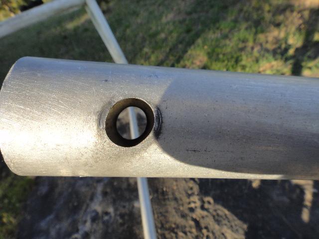
The element holes for the Reflector and last director of the boom both became oval in shape after being left alone for far too long.
There were warning signs of what was going on but I ignored them as I thought the Delron insulators and not the boom was being chewed up, boy was that a mistake. Those delron insulators are tough customers.
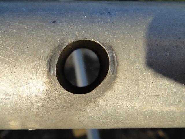
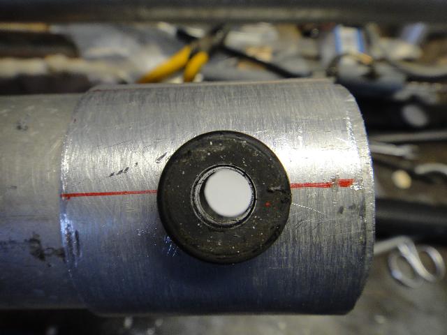
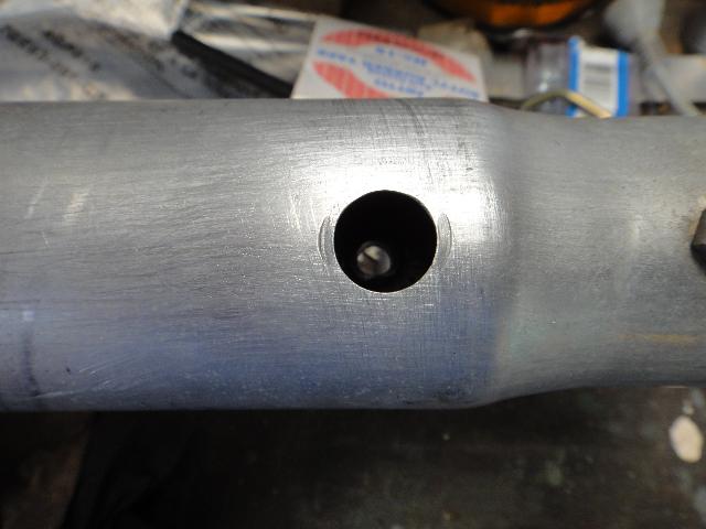
Close up of the oval hole.
Nothing is that simple, it would seem the new insulators are even a slight bit smaller that the originals, sigh (again)
Okay first job is to find a way to fix those oval holes. A few on air discussions turned up some good ideas (thanks Brian and Richard) for your input. It all started with the idea of creating a sleeve over the problem area, one idea was to create two half shells (like used in a car engine bearing) that can be positioned over each problem hole. Then once in place use either screws of rivets to secure them from moving.
This is how I started to attack the task but was side tracked by the thought of creating a single sleeve from some 50mm tube and cutting a single slit lengthwise to allow it to expand over the existing 50mm boom. While it would be fiddly to get the holes in the right spot, it seemed to offer a better long term solution in my mind as it would hug the existing boom when sprung outwards to slide over the original. Plus I did not have a 15mm dril bit so I could afford a few experimental holes in my test sleeve to work out where they should go :-)
The test sleeve was cut from the length of Ali tube with a hacksaw and boy was that a mistake, I wandered all over the place which had a flow on effect when trying to make accuracte measurements for the holes. So on the way home on the next day I bought a tubing cutter that can handle 60mm tube (had promised this to myself for many months but could not justify it until now, as a new M2 yagi costs a lot more than I want to spend at present)
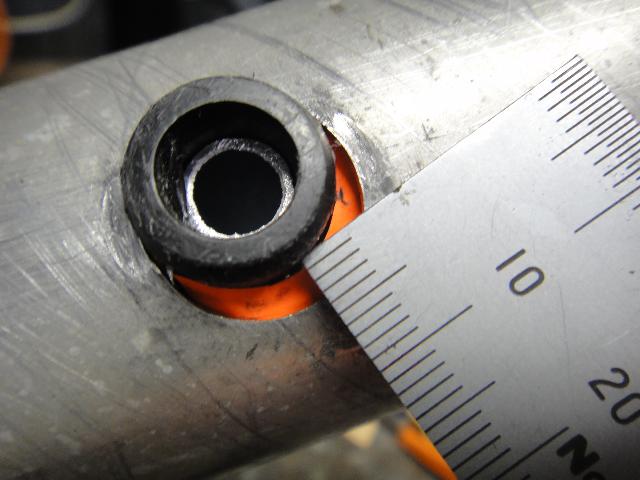
Just so you get and idea how bad the ovaling of the hole was, I put some coloured paper behind the insulator and that a rule reading in milimetres.
The Sleeve
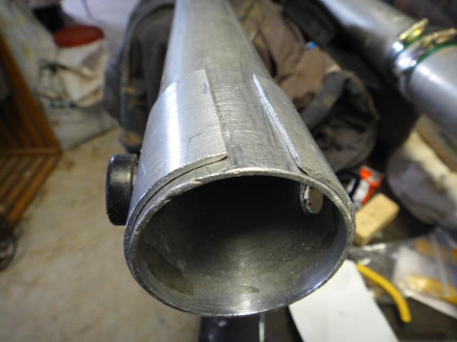
The first test sleeve for the boom, not a pretty sight but it proved I could do it.
You can see the remains of the oval hole on the far side of the original boom when you look through it from this side.
Element insulator in place (boom rotated 180 deg from previous image in case your wondering)
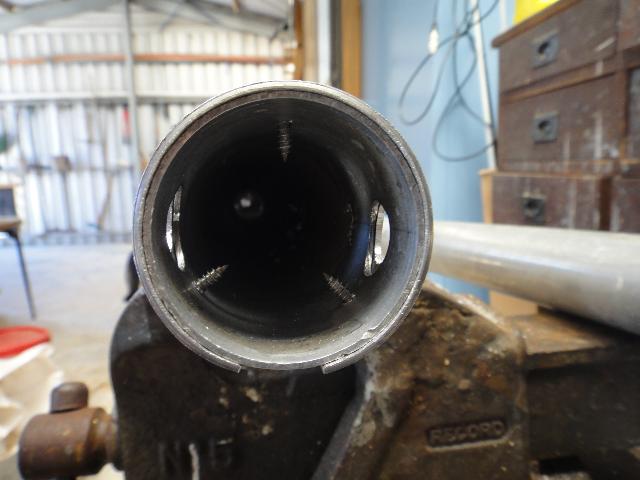
The end view of the test sleeve, I am hoping this method will allow the yagi to get back up in the air before DX0DX comes on air
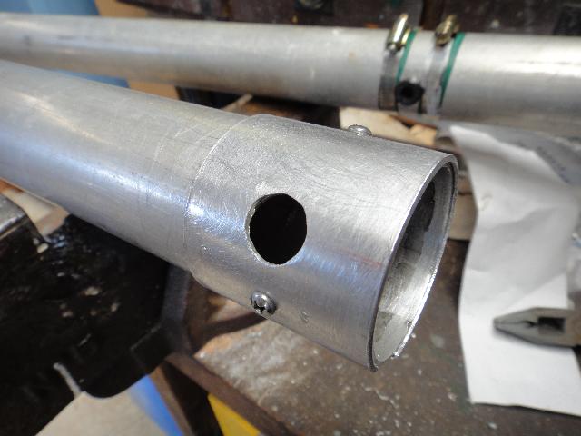
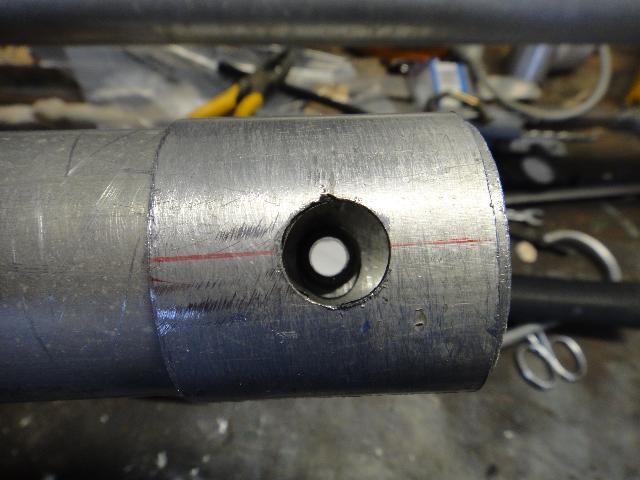
After my success with the test sleeve here is the real thing that was sliced with the tubing cutter.
Three stainless self tappers to secure the sleeve in place
The Shims
Next job is to work
on the slightly oversize holes along the remainder of the boom, I had
all sorts of thoughts on how to do this and finally settled on cutting
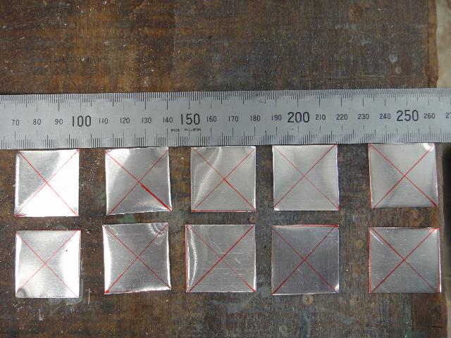
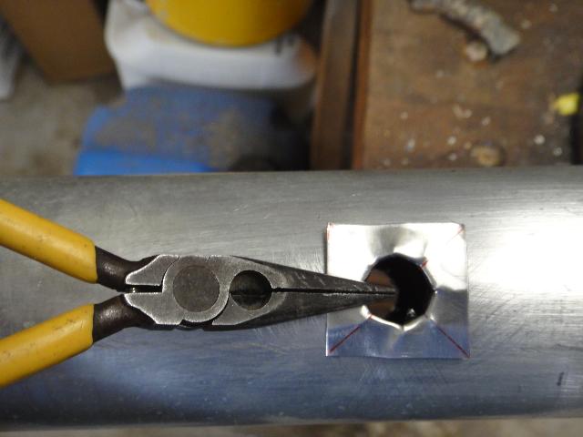
30mm squares of thin aluminium sheet I bought from one of the hobby
shops to create a shim for each hole. X marks the spot where I hit it
with the centre punch to creat the initial hole, from there I cut
outward along the lines to create flaps that can be bent down into the
hole. I hope the photos will show this a bit better than my words.
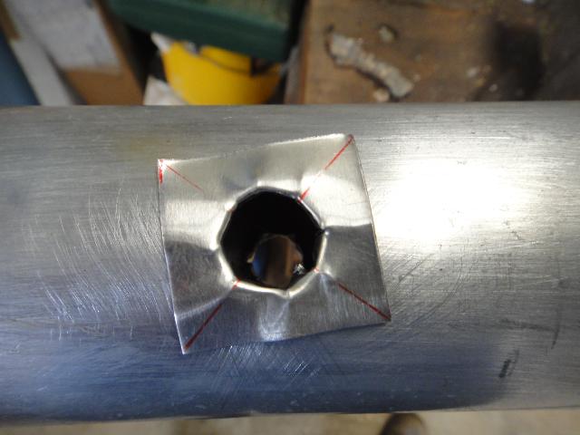
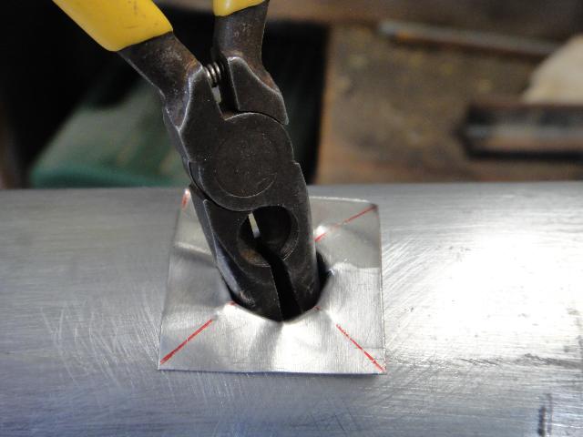
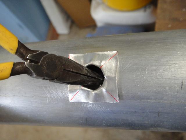
After the shim is worked to shape with a tapered tool, make sure the outer edges of shim mould to the boom, using a hammer and a block of soft wood.
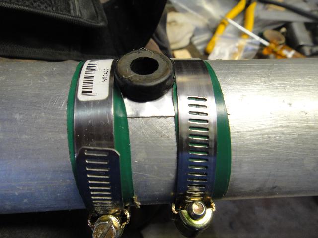
On each hole the outer edges of the shim is glued in place. I use the wormdrive clamps to keep them tightly in place while the glue sets. The worm drive clamps are then removed to reveal a neatly formed repair. The element insulators are hammered into place to ensure a snug fit. I want to avoid any future repeats of the loose elements.