Tower information
(One Man Tower)
In 2019 after a bit of trauma a rethink of the EME tower project
happened, I abandoned the cut down southern cross tower in favour of
three sections of a One Man Tower (OMT) that was purchased from an
advert on VKClassifieds
So in a mad minute I answered the advert and said Yes, then paid the
price of a small used car for the tower and its assembly
accessories. What did not come of course was the steel work that
goes into the concrete footing, I searched high and low for information
on the WWW about footings for an OMT but found zippo about them, seems
no one ever published that information.
Luckily another VK5 sent me some photos of what was used at his bush
block for his OMT so now I at least had an idea what another had done for their tower.
In the end I did turn up two PDF scans of what seem to be original OMT
documents
Footing Dimensions
General Engineering
I used the information in the Footings document to size the hole needed
for my tower and the size of the steel work needed to keep the concrete
happy.
In my case I settled on a hole 2.4M x 2.4M x 1.0M deep, which equated
to 5.7 cubic metres of concrete
The design of the steel work took quite a bit of time and I found I had
to get to know how to use a drawing program so the design could be
interpreted by a local engineering works
I
am not sure if all OMT's are the same but my bottom section had a
second set of holes in the bottom angles, this second set were all 20
mm diameter holes. My tie down hardware was made to take
advantage of these extra 20 mm holes.
I did not take any photos of the reo cage on it own, which was a silly
mistake. here is a screen capture of my very basic CAD drawing.
Please note, I
have removed all of the dimension data from this drawing.

Fig 1. Cad was never my thing.
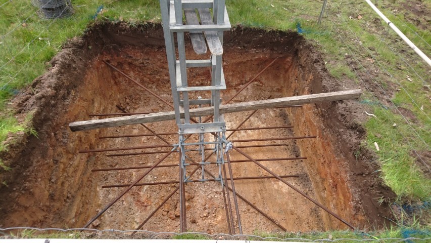
Fig 2. First trial of the cage in the hole with bottom section attached.
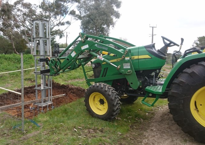
Fig 3. Our John Deere tractor was a great tool for this, the forks made
things so much easier.
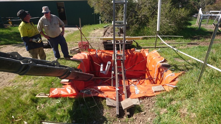
Fig 4. The big day, concrete is going in the hole (feeling nervous) in
picture, the concrete delivery driver and my friend Andrew. you can see
the 100mm conduit in this picture headed back to the shack.
Yes the hole is lined with builders plastic to protect the concrete from erosion by the soil, which apparently
is a real problem
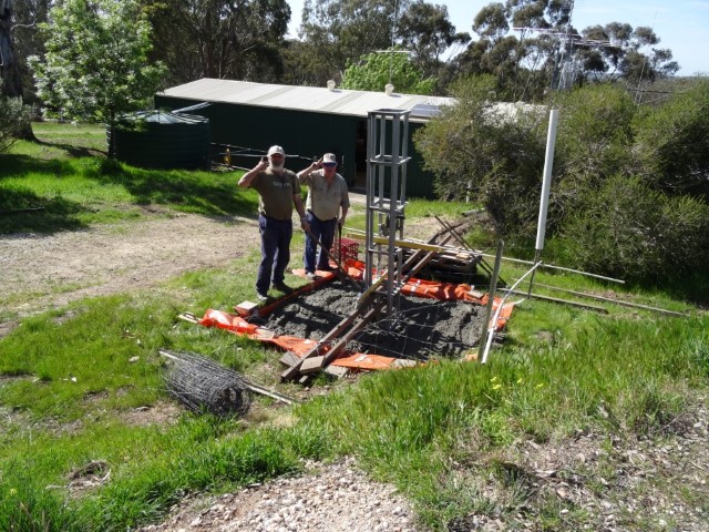
Fig 5. The workers Salute, still have some work to do yet on the
finishing off, thanks Andrew for keeping me on track.
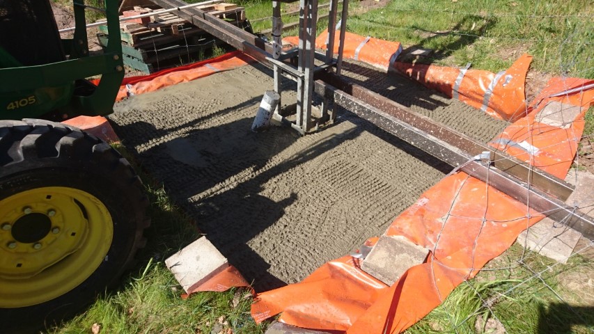
Fig 6. A rough non slip finish, yes that is a 100 mm pipe for the
cables from the shack.
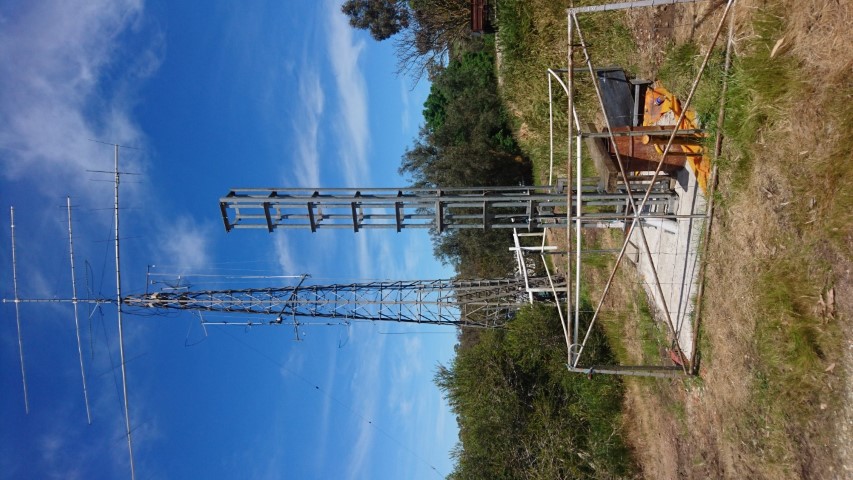
Fig 7. The concrete is in and had a few days to cure, southern cross
main tower in the background.
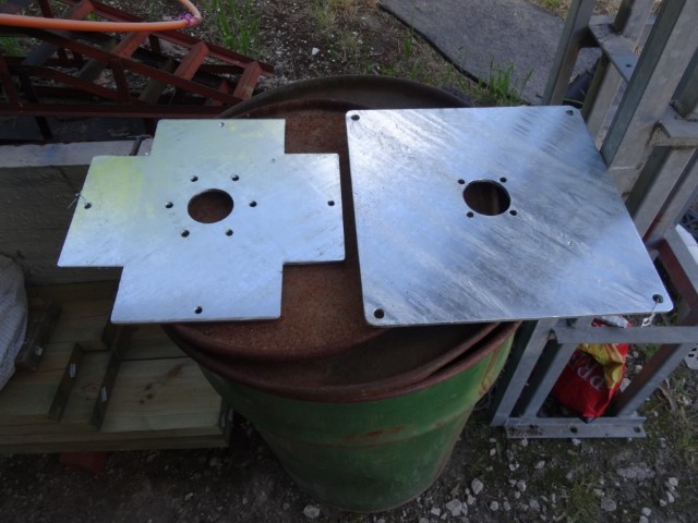
Fig 8. I am not using the hazer for the antennas so these plates fit
onto my 'top section' to give me traditional rotator and bearing mounts
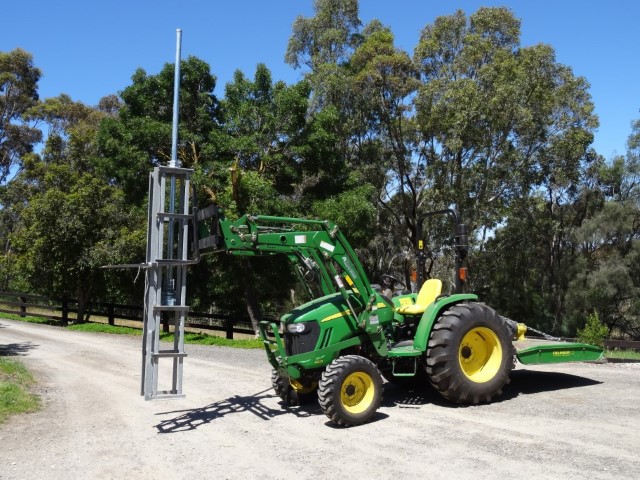
Fig 9. the top section on the move after the plates are bolted into
place. It is a Create RC5B-4P Heavy duty rotator and a Yeasu thrust
bearing, that is 60mm O.D pipe (50mm nominal bore)
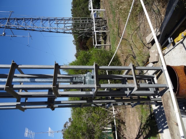
Fig 10. top section ready to be winched up, waiting for a calm day as
it is now way heavier than a standard section :-)