A case for the Larcan 1KW.
Now that I have some RF out, a case to provide some shieldng from EMR is a must but how to do it without making it the size of a telephone box. I had some scrap 2mm and 1.6mm Ali sheet on hand so a quick trip to a guilotine at my work place gave me two strips for the sides (1.6mm) and a strip for the rear (2mm). Now the height of the sides and rear were restricted by what was on hand at the time, I want to mount the RF change over relays (flat rectangular NARDA's) poking out of the rear panel.
So here is the Mark 1 rear panel and sides for my Larcan. I will use this first case to flesh out the design problems and then try an incorperate the output connector mod into the new rear panel.
Peter, June 2012
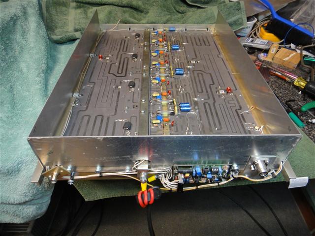
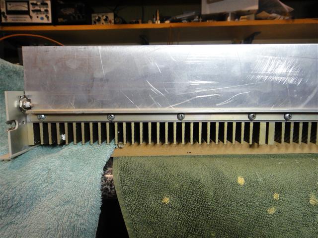
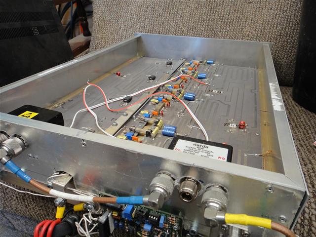
Side panels are slid down between the
heatsink and the mountin rails, then holes drilled in the sheet and the
original screws passed through it, ends up with nice and strong
mount.
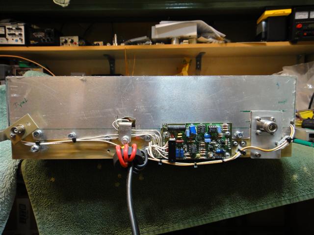
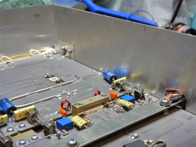
Rear corner, will have ali angle bolted on the inside to join the two sections of sheet
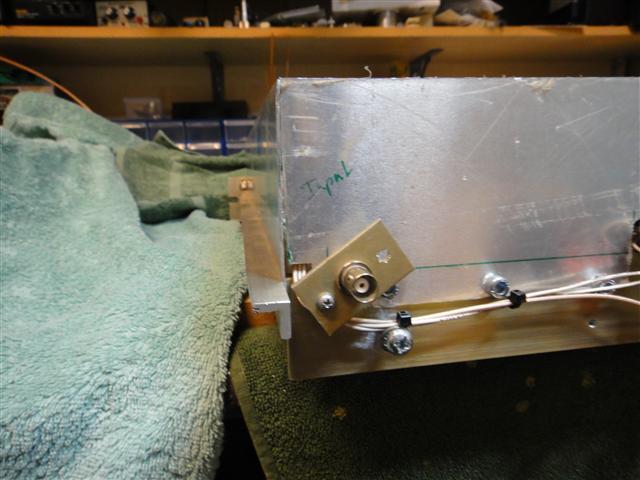
Input connector can now be angled so
the centre pin aligns with the PCB input track, which allows the
original hole to be used to secure the rear panel.
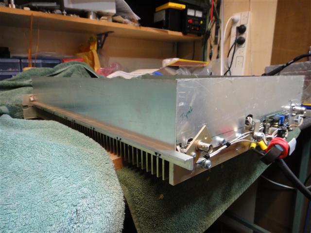
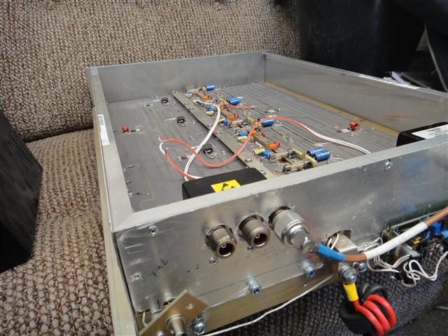
Side view, output port coax needs to be removed and the coax passed through a new hole if you want to retain the monitor port.
On the otherside the green status light must be removed.
On the otherside the green status light must be removed.
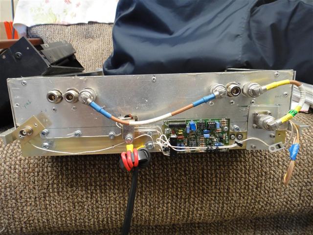
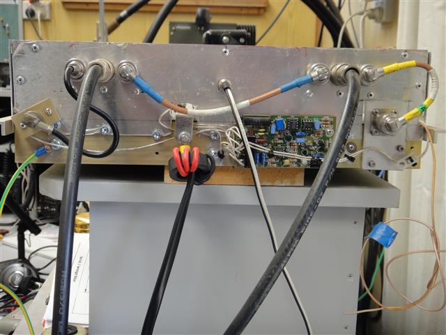
Input port (left side as you look at it in the photo) has been angled to align BNC centre pin with PCB track to reduce stray RF.
Green wire on left is earth to the HP switchmodes case. Black and white wire is PTT from the rig, thee are some left overs on the right side from the deleted output monitoring port
What would I change?
Given
the chance to do the rear panel a second time, I would have opted to
integrate the new output connector into the panel and not had the
fidgety cutout for the earlier output connector mod, this would give
better rigidity and a better RF seal. Other than that the side panels
being held in place by the side rails works well and was simple to put
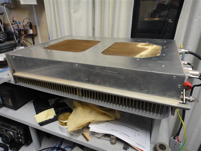
in place along with the new front panlel made sense.No fans yet on the heat sink
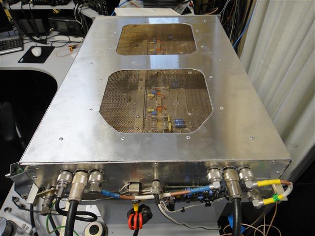
The bronze fly wire is held in place with some light gauge aluminium bar and pop vivets, while there is no intention to force air cool the components section I want there to be a path for natural air flow that also kept the RF in its place (inside the case)
Maybe then I can move on to the Mark II version which uses different input and output combiners.